Product Details
Products Name:C6 Bench Lathe
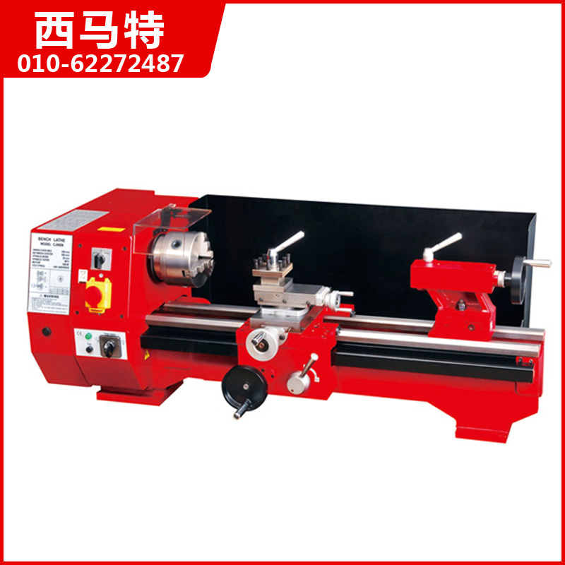
Key Feature:Near silent running
Integral splash guard
Metric and Imperial thread cutting
Full range of accessories available
Converts to a multi-purpose machine with the milling attachme
Medium capacity, high quality lathe suitable for workshop or school use
Specifications
Swing over bed 250 mm
Distance between centers Model 400 400 mm
Model 550 550 mm
Hole through spindle 20 mm
Spindle taper MT3
Tailstock taper MT2
Spindle speed(6 step) 125-2000 rpm
Compound travel 75 mm
Cross slide travel 110 mm
Motor output power 550 W
Thread of range Metric version 0.4-3.0 mm (12 threads pitches)
Imperial version 10-44 TPI ( 8 threads pitches)
Overall dimension (LxWxH) Model 400 1040x600x450 mm
Model 550 1140x600x450 mm
Weight (Net/Gross) Model 400 125/160 kg
Model 550 145/180 kg
Packing size (LxWxH) Model 400 1140x600x450 mm
Model 550 1170x640x580 mm
Optional Accessories
|
编号
Serial No. |
名称项目
Item Description |
图片
Picture |
适合车型
Suitable for Models |
|
S/N:10239 |
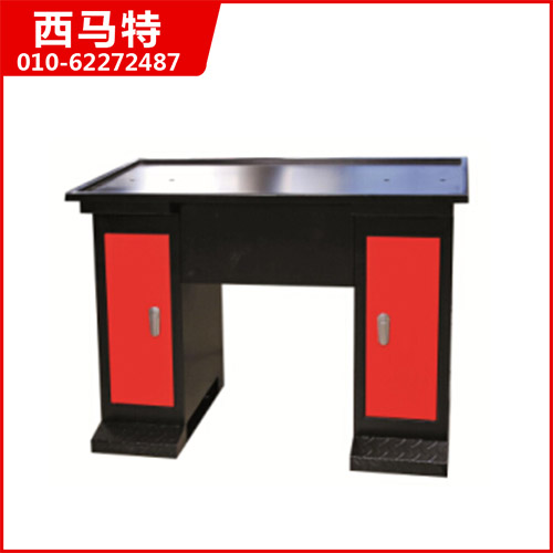
车床底座
Stand for Model 550
Overall demension: 1040*425*770mm |
|
C6,C6B,SC6,M6 |
|
S/N:10019 |
|
|
C6,C6B,SC6,M6 |
|
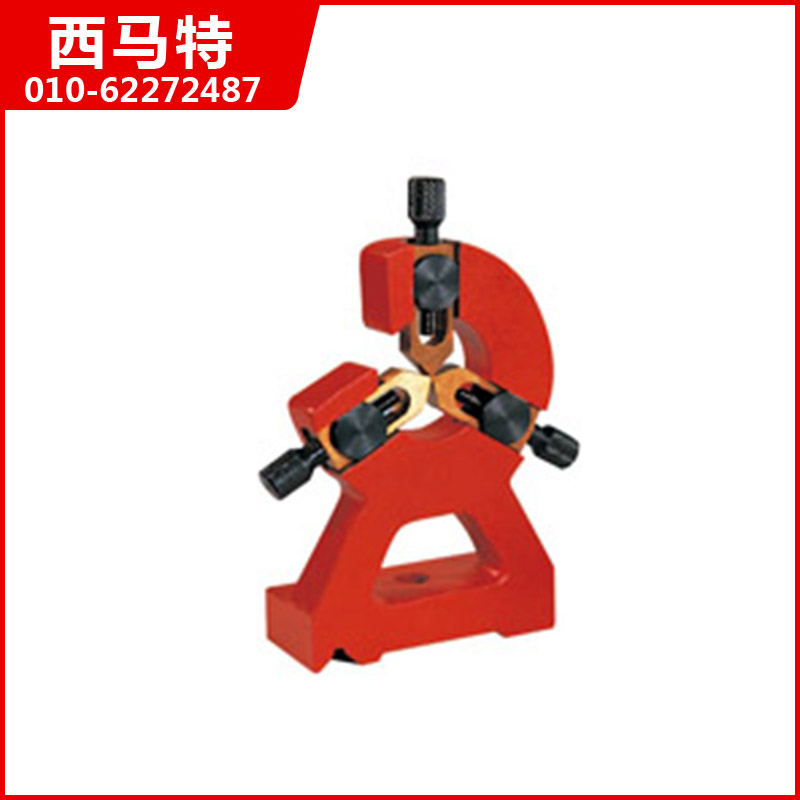
S/N:10020 |
跟刀架
Follow rest |
|
C6,SC6,C6B,M6 |
|
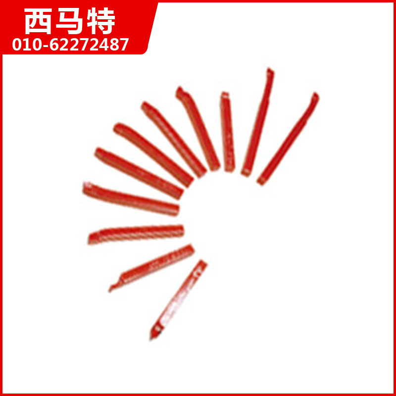
S/N:10022 |
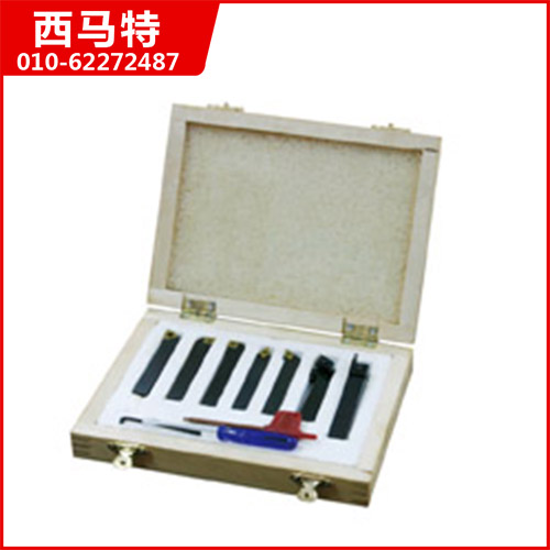
车刀Cutter 11 pieces set
DIN 4971R外圆偏车刀
DIN 4972R弯头45度车刀
DIN 4973R内孔车刀
DIN 4974R内孔平面车刀
DIN 4975 外螺纹60度车刀
DIN 4976 宽刃光口刀
DIN 4977R外圆90度偏刀
DIN 4978R端面90度车刀
DIN 4980L外圆左车刀
DIN 4980R外圆90度偏刀
DIN 4981R切断刀 |
|
C4A,C4B,SC4,C6,
C6B,SC6,SM4,M6 |
|
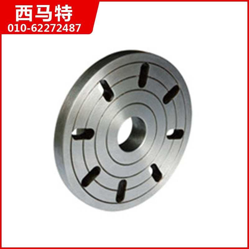
S/N:10023 |
花盘
Face plate ¢220mm
|
|
C6,C6B,SC6,M6 |
|
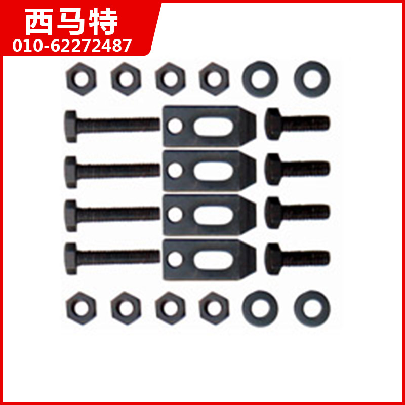
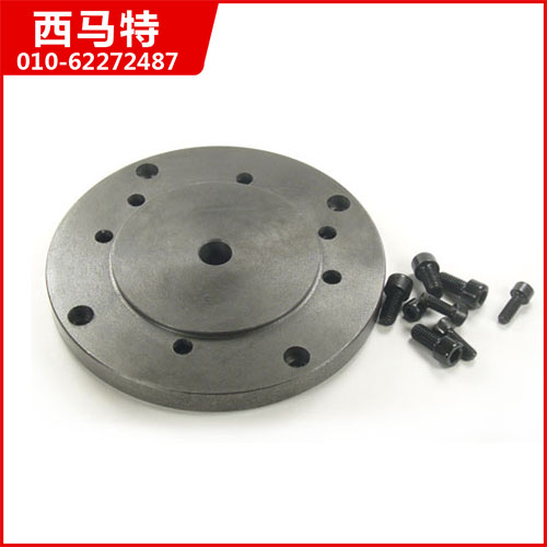
S/N:10023A |
花盘螺丝组件
Clamping kit for face plate |
|
C6,SC6,C6B,C8,M6,M8 |
|
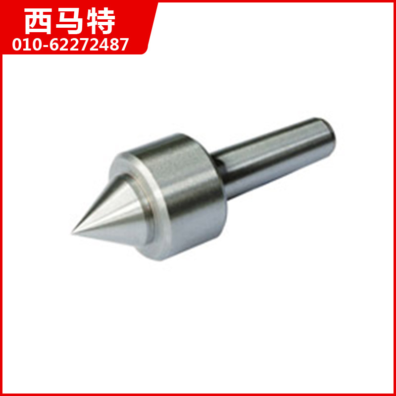
S/N:10024 |
活络顶尖
Rolling center
MT#2 |
|
C6,SC6,C4A,SC4,
C6B,C8,SM4,M6,M8 |
|
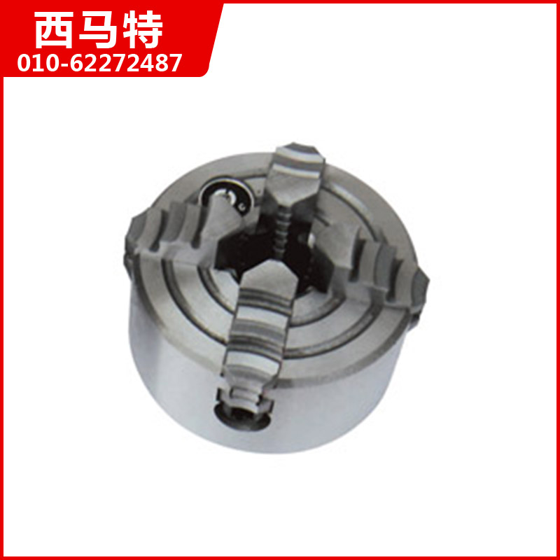
S/N:10025 |
四爪卡盘
4-jaw chuck ¢125mm |
|
C6,C6B,SC6,SX4 |
|
S/N:10025A |
四爪卡盘和法兰连接器
4-jaw chuck ¢125mm with flange |
|
C6,SC6,C6B,M6 |
|
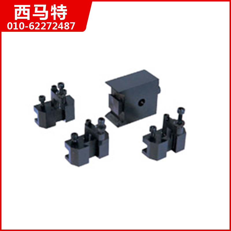
S/N:10026 |
快换刀架
Quick change cutter rest |
|
C6,SC6,C6B,M6 |
|
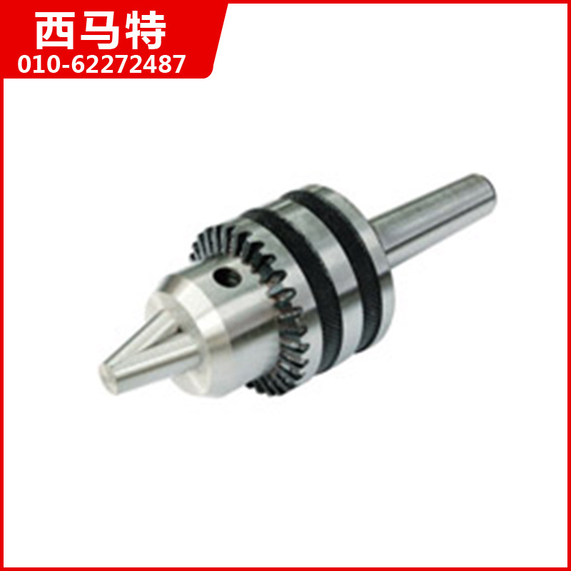
S/N:10027 |
尾座钻夹头和锥柄
Tailstock chuck
Dia.13mm+MT#2 |
|
C4A,C4B,SC4,C6,C6B,
SC6,C8,SM4,M6,M8 |
|
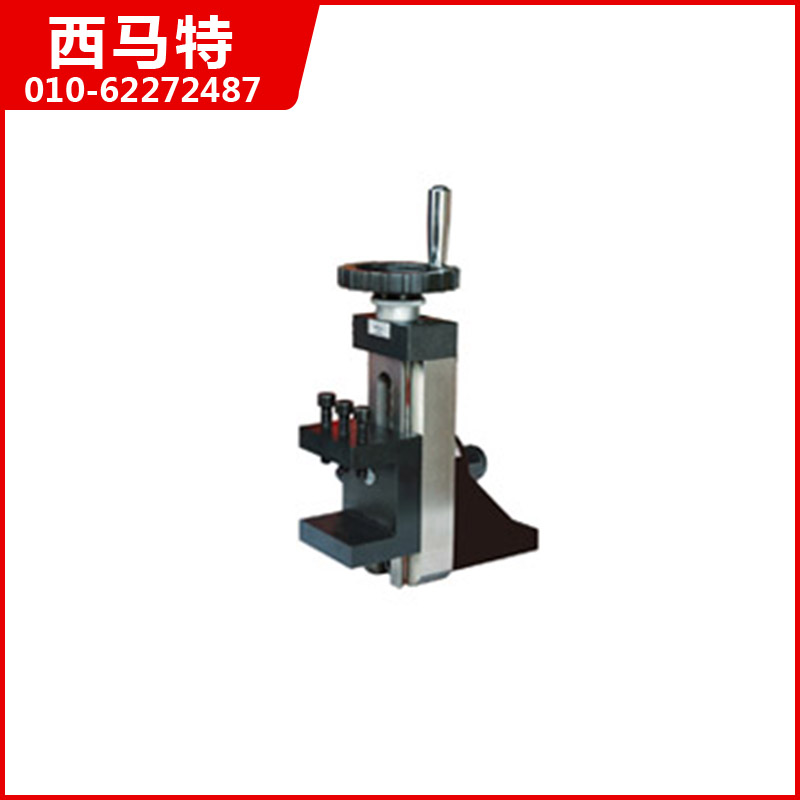
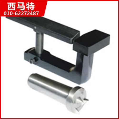
S/N:10060 |
垂直托板
Vertical slider
|
|
C6B,C6,SC6 |
|
S/N:10063 |
木工附件和中心顶尖
Wood toolrest with center |
|
C6B,C6,SC6 |
|
S/N:10131B |
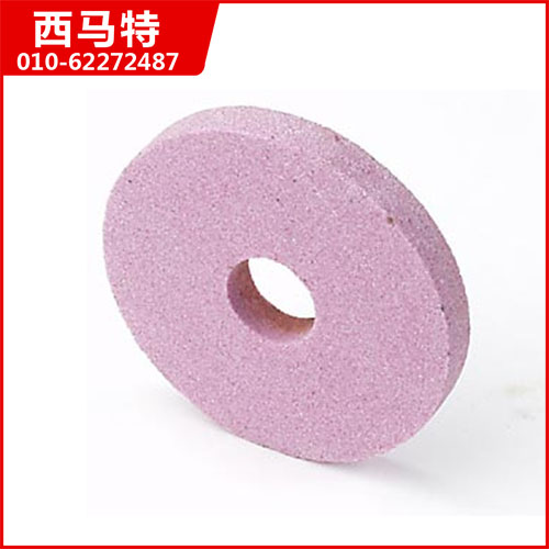
磨削附件
Grinding attachment
Spindle speed 0-6000±10%rpm
Wheel size 80*20*10mm
Motor output power 250W
Net/Gross weight 4/5kg |
|
C6,SC6,C6B,M6 |
| S/N:10131-1 |
砂轮片
Wheel replacement |
 |
C6,SC6,C6B,M6 |
|
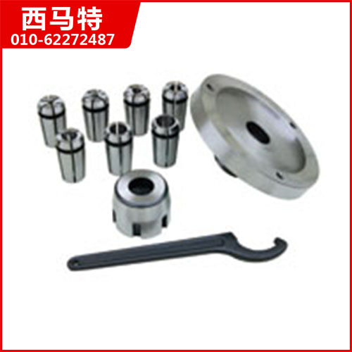
S/N:10149 |
弹性夹头组(公制)
Mill chuck set(metric)
Chuck dia. 4, 6, 8, 10, 12, 14, 16mm |
|
M6,C6B,C6,SC6 |
|
S/N:10149A |
弹性夹头组(英制)
Mill chuck set(Imperial) |
|
M6,C6B,C6,SC6 |
|
S/N:10151 |
数显套件
DRCD kit |
|
C6,SC6,C6B,M6 |
|
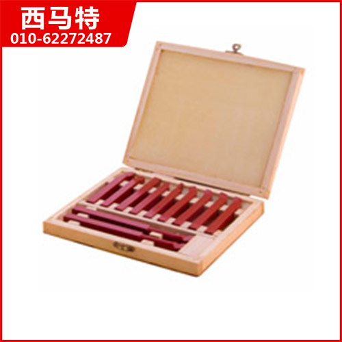
S/N:10198 |
车刀Lux cutter set with box
10x10 mm
DIN 4971R外圆偏车刀
DIN 4972R弯头45度车刀
DIN 4973R内孔车刀
DIN 4974R内孔平面车刀
DIN 4975 外螺纹60度车刀
DIN 4976 宽刃光口刀
DIN 4977R外圆90度偏刀
DIN 4978R端面90度车刀
DIN 4980L外圆左车刀
DIN 4980R外圆90度偏刀
DIN 4981R切断刀 |
|
C4A,C4B,SC4,C6,C6B,SC6 |
|
S/N:10201 |
组合车刀
Cutting set 10mm(Tin Coated)
DIN 4977R 外圆90度偏刀
DIN 4980L 外圆左车刀
DIN 4980R 外圆90度偏刀
DIN 4975R 外螺纹60度车刀
DIN 4981R 切断刀 |
|
C4A,C4B,SC4,C6,C6B,SC6 |
|
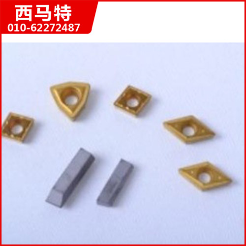
S/N:10201-1 |
可换刀头
Tip replacement |
|
C4A,C4B,SC4,C6,C6B,SC6 |
Review
Table of Contents
- Introduction
- General Construction
- Headstock and Chuck
- Chuck and Chuck Mounting
- Motor and Electronics
- Drive Train
- Cross-Feed and Compound
- Carriage and Saddle
- Tailstock
- Enhancements
- Conclusion
 Sieg C6 Lathe Sieg C6 Lathe
Introduction (04/18/07)
For many of us who started out with the mini-lathe, a larger, more capable lathe eventually becomes a "must-have" item. The mini-lathe is a great little machine within its limitations, but you just can't turn an 8" workpiece on a 7" lathe. (Well, someone out there has probably added riser blocks to the 7x to turn 8" stock! :). Even with work in the 4" diameter range, you start to reach the practical limits of the 7x minis as lack of sufficient torque and toolpost reach start to make things difficult. Often you can work around these shortcomings with some ingenuity and specially made adapters and modifications, but sometimes you just want to work on the project at hand, rather than the lathe.
Like many things in life, as you gain experience and skill, the tools that got you started eventually limit your ability to advance to the next level. So it was that about two years ago, I began looking for a larger lathe to accommodate my growing needs. I found the C6 listed on the Sieg website and was able to work out a deal to import one directly from the factory. Shipping was expensive and there is no after-the-sale support, so that is not a solution I would recommend to others, but suited my needs at the time.
I wanted to show the relative size of the C6 compared to the mini-lathe. This next photo will give you some idea, but keep in mind that the mini-lathe is in front of the C6, which, being closer to the camera, makes the mini-lathe look disproportionately large, so the real difference in size is even greater than the photo implies..
 C6 shown with 7x12 mini-lathe C6 shown with 7x12 mini-lathe
I've had the C6 in my shop for over two years, but until recently, I was not aware of any U.S. distributors for it. I didn't want to publish a review only to have readers contact me asking where they could get one. A few days ago, while browsing the ToolsNow.com (formerly Cummins Tool) website, I discovered that they now stock the C6 lathe as Item# 7900. I have also seen it listed on eBay as a Shop Fox M1016. So, it seemed like a good time to move ahead with the review.
(Note: ToolsNow.com also has a good deal on the mini-lathe at $399.99 (04/07) with quite a few accessories included)
Another option is a C6 lathe combined with a mini-mill mounted on the bed. This intriguing machine is sold as the Grizzly G0516. My own preference leans strongly towards having separate machines for milling and lathe work, but for some hobbyists with limited space, limited budgets and the time and patience to switch between lathe and milling modes, combination machines can be a good choice. You get a lot of capabilities in a compact package, at a price that is often significantly less than the cost of separate machines.
 Grizzly 0516 - C6 lathe combined with the X2 mini-mill Grizzly 0516 - C6 lathe combined with the X2 mini-mill
Like the mini-lathe and mini-mill, the C6 lathe is manufactured by Sieg Industrial in Shanghai, China. While the construction and finish are similar in some ways to their smaller cousins, the C6 is more rugged, more precise and has some extra features, such as an abundance of oil ports, that make it a better-quality lathe overall.
Included with the lathe are a 5" 3-jaw chuck, #2 and #3 Morse taper dead centers and the usual assortment of metric open-end and hex wrenches for making adjustments.
General Construction
In many respects, the C6 is like the 7x12 on steroids - Lots of steroids! Let's take a look at some of the important dimensions:
| Dimension |
C2 7x12 |
C6 10x22 |
| Swing over bed |
7" |
10" |
| Swing over cross-slide |
4" |
5 1/2" |
| Distance between centers |
12" |
22" |
| Standard chuck |
3" |
5" |
| Maximum chuck |
5" |
8" |
| Weight |
80 lbs. |
320 lbs. |
Perhaps the most telling figure is the weight. As you scale up a machine, the strength, and thus the weight, increase faster than the linear dimensions. In machine tools, weight is a desirable characteristic. A heavier machine is more stable, more rigid and can handle heavier loads without overstressing the structure. In practical terms, that translates into being able to work with larger materials and take more aggressive cuts to get the job done quicker.
In all but the smallest of lathes, cast iron is the primary ingredient for the bed, carriage, headstock and tailtock. The castings on my C6 are pretty clean and free from sharp edges and unfinished areas. As in any casting, due to the nature of the casting process, there are some rough areas on the hidden and inner surfaces, but these have no effect on machine operation. All of the surfaces, including the hidden ones, are painted to resist rust, with a light-yellow color being used on some of the inner hidden surfaces.
 Cast iron bed and ways Cast iron bed and ways
The ways are precision ground to a double-prismatic shape - i.e. there are prism-shaped raised guides on both the front and back sides. I could find no indication on the lathe or in the manual that they are hardened, so I assume that, as on the mini-lathe, they are not. This should not be a concern as long as care is taken to avoid dropping tools, chucks or big pieces of raw materials on them, causing dents and dings.
On the left end of the lathe, a hinged sheet-metal door swings open to provide access to the speed-change belts and pulleys and the gear train that determines the leadscrew speed for power feed and thread cutting. A heavy-duty sheet metal chip shield, painted black, extends along the full length of the back side of the lathe and does an excellent job of preventing chips from flying away from the back of the lathe into areas of the shop that may not be easily accessible for cleanup. Another chip shield, along the front of the lathe, protects the lead screw from becoming clogged with chips - a nice feature.
 Safety door opens to expose drive train Safety door opens to expose drive train
A number of safety features are standard on the C6 - including an interlock switch that disables the motor when the drive train access door is opened.
Headstock and Chuck
 Headstock with stock 5" chuck and safety cover Headstock with stock 5" chuck and safety cover
The spindle is a made from single piece of metal that extends through the headstock, the two bearings that support it, and out the left side of the lathe, where the drive pulleys are mounted on the far end. Long stock up to 3/4" diameter can pass through the spindle bore, which has a #3 Morse Taper for holding centers or other accessories.
 Spindle passes through headstock bearings Spindle passes through headstock bearings
As the "business-end" of the lathe, the headstock construction is important in determining the overall accuracy of the lathe. If the spindle is not precisely machined or the bearings that support it are of poor quality, the spindle will "wobble" by a small amount - perhaps less than one one-thousandth of an inch - but this small variance will mean that no workpiece turned on the lathe can be any more accurate than that. Therefore, variations, known as "runout" or "TIR" (Total Indicated Runout) should be no more than a few ten-thousandths of an inch on a good-quality lathe.
 Measuring spindle runout Measuring spindle runout
Runout is measured using a sensitive dial test indicator (DTI) on the inner surface of the spindle taper. I was pleased to find the runout on the lathe I am reviewing to be about 0.00016", or less than two ten-thousandths of an inch, as measured by a good-quality Peacock brand DTI calibrated in divisions of "tenths", or 0.0001". Runout measured at the surface of the raised spindle boss was also under two tenths. Not bad for a lathe selling for less than $1000.
Chuck and Chuck Mounting
Standard on the C6 is a 5" 3-jaw chuck. Like all of the chucks I have used on the mini-lathe this one is well-made. The mounting system is interesting, comprising a machined cast iron backplate with three mounting studs and their corresponding nuts.
 Chuck back plate and mounting studs Chuck back plate and mounting studs
The nuts stay on the studs at all times and pass through the large holes in the spindle face. On the back side of the spindle face is a steel disk about 3/16" thick, that rotates through an arc of about 30�. Keyhole-shaped holes in the plate are aligned along the arc such that the nuts pass through the large part of the keyhole but are too large to pass through the small part, which is just a little larger than the stud diameter. Once the locking plate is rotated into position, the nuts are tightened down to lock the chuck in place.
  Chuck locking plate in open and closed positions Chuck locking plate in open and closed positions
 Tightening the chuck mounting nuts Tightening the chuck mounting nuts
Chuck Key Safety Interlock
Always present when working with a lathe, is the danger of accidentally leaving the chuck key in the chuck. If the lathe is powered on in this situation, the chuck key will become a heavy, fast-moving projectile that, at best, will break something in the shop, or at worst could be fatal if it strikes you in the head. For this reason, experienced lathe operators often advise: "never remove your hand from the chuck key when it is in the chuck." On smaller chucks, such as used on a drill press, it is fairly common on newer machines that the chuck key has a spring-loaded tip to enforce this rule - release your grip on the chuck key, and it pops out of the chuck. That solution is less practical on a large heavy chuck key such as is used on a lathe chuck. In any case, you don't want the chuck key to pop out and fall on the ways, possibly leaving a large dent in the precision-ground ways.
Sieg has provided a practical solution on the C6: a heavy-duty plastic cover engages a spring-loaded motor interlock switch (inside the headstock, as seen in the photo above). In order to insert the chuck key into the chuck, you must first raise the plastic safety cover, thereby engaging the switch and preventing the motor from running. In fact, raising the cover trips a relay that must be reset by pressing the green reset switch (more on this later) under the yellow safety cover.
 Adjusting the chuck with interlock cover raised Adjusting the chuck with interlock cover raised
One disadvantage to this particular solution, is that it will not work with chucks larger than about 6". Since I recently ordered an 8" 4-jaw chuck, I'll have to think about a way to modify the safety interlock to accommodate the larger chuck.
Motor and Electronics
A robust AC motor rated at 550 watts, or about 3/4 HP, powers the lathe. Unlike some motor power ratings I have seen, I think this one is pretty honest. In any case, it provides plenty of power for anything you are likely to do on the C6. When taking some heavy facing cuts on a 6" diameter disk, I found that the cogged drive belt skips if you overload the lathe, but the motor does not bog down.
 Heavy-duty AC motor powers the lathe Heavy-duty AC motor powers the lathe
Unlike the mini-lathe, the C6 does not have electronic variable speed control. I miss the convenience that it provides, but electronic variable speed controls are typically found only on DC motors of 1/2 HP ratings or less. As you get up into the heavier duty motors, the cost becomes prohibitive for a moderately priced lathe within reach of the hobbyist's budget. Changing belts is a nuisance, but like an old VW ad used to say about their manual transmissions: "after a while it becomes automatic."
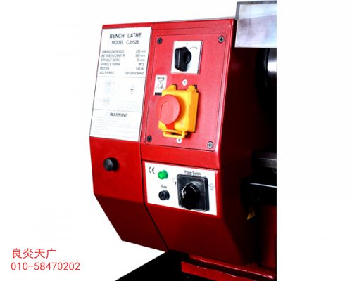
Conveniently mounted on the front panel of the headstock, the electronic controls are straightforward in operation. Down below, we have the green power on/off pilot light, the fuse holder, and the main power switch. Providing for the combined mill/lathe version of the C6, the power switch has three positions:
- Cutting - normal lathe operations
- 0 - power off
- Milling Drilling - directs power to the milling head on lathes so equipped
 Power control panel Power control panel
On the upper panel are located the motor direction control switch and emergency power ON/OFF switch.
 Direction switch and emergency cutoff Direction switch and emergency cutoff
Uppermost on the panel is the motor on/off and directional switch. Turning it to the right causes the spindle to rotate in the normal, counter-clockwise direction; turning it to the left reverses the motor and spindle rotation for special applications. In my work on the lathe, I have used the directional switch primarily for reversing the lathe at the end of each pass when cutting threads.
On the C6, the emergency power cutoff switch is a little different than the ones on the mini-lathe and mini-mill. Under the hinged cover are two buttons:

For those not familiar with the mini-lathe, here's how it works. The hinged yellow cover has a spring-loaded catch that locks it shut. In normal operation the cover is left loosely open, with the cover in the down position. Should an emergency occur while the lathe is running, a quick punch on the red cover button shuts off the lathe and resets the interlock relay. To restart the lathe, you must first open the cover and press the Green button to reset the relay and restart the lathe.
Raising the chuck-key interlock shield or opening the drive train access door also trip the relay to ensure that the lathe is not accidentally restarted while the chuck key is in place or the drive train is being modified. While either interlock is active, pressing the Green start button has no effect.
Oddly, all along, I have been using the motor directional switch to turn the motor on and off. Until writing this review today, I had not really thought about using the green button for that purpose (Duh!). If I can offer any excuse, I suppose it is that I'm conditioned from years of operating the mini-lathe and mini-mill, which don't have a green button under the cover - just a Stop button. Well, now that I know about it, I guess I'll have to get used to using it.
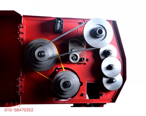
Drive Train
Powered by the 3/4 HP reversible AC motor, the drive train provides six rotational speeds, from 150 to 2400 RPM. The range of speeds is convenient for most work, although I use the highest speeds only occasionally for polishing operations. It would be nice to have a lower speed, say around 30 RPM, for threading. I might rig up another reduction pulley someday for that purpose.
 Speed-change chart Speed-change chart
 Belt and pulley drive train Belt and pulley drive train
Speeds are selected by moving the V-belt among different pairs of pulleys. A separate toothed belt, which is never moved, drives the speed-reduction pulleys. An idler arm, with a ball-bearing supported roller, maintains tension on the drive belt. It must be loosened in order to change the belt position, then re-tightened. For safety, a roller-switch, seen above the belt near the top of the lathe, disables the ON switch while the drive train access door is open.
 Idler arm and roller bearing Idler arm and roller bearing
While clearly not as convenient as a variable-speed control like that on the mini-lathe, changing the belts is not too troublesome once you get used to it. To make the process a little quicker and more convenient, I made some dedicated handles (see Modifications section later in this article) to replace the bolts that are frequently used.
Lead Screw Drive Gears
Power feeding of the carriage for turning under power and thread cutting is driven by a set of steel change gears. When power feed is not in use, the gear train support arm can be rotated to the right so that it is disengaged. This is handy when the gears are set up for thread cutting, but not needed for the work being done at the moment.
 Drive train gears and retaining components Drive train gears and retaining components
Combinations of gears are selected and mounted onto gear shafts according to the desired feeding speed, as detailed on a chart on the front of the drive train access door. Although I have not confirmed it, I would assume that, as on the mini-lathe, additional thread pitches are possible using gear combinations not shown on the chart. Left-handed threads can be turned by installing the idler gear, shows in the center of the photo, to reverse the direction of the leadscrew rotation.
 Threading gear selection chart Threading gear selection chart
 Power feed gear selection chart Power feed gear selection chart
Setting up a gear train takes a little practice to get all the gears in the right positions and with the right amount of mesh between the teeth. It's actually a little simpler on the C6 than on the mini-lathe, though, because all the gears stack in the same vertical line. On the mini-lathe, you also have to adjust the arc.
 Moveable shafts for mounting gears Moveable shafts for mounting gears
Setting up a gear train for thread cutting
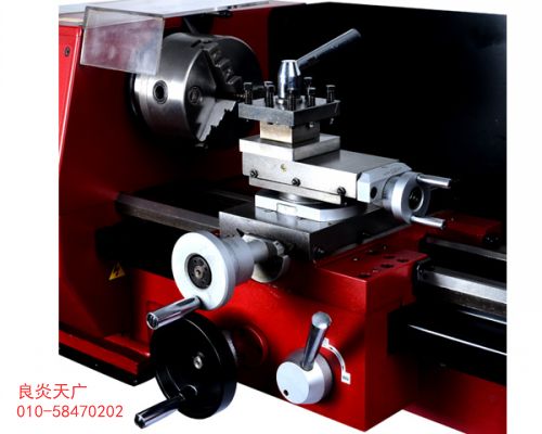
Cross Feed and Compound
In normal operations the cross feed may well be the most frequently used component of the lathe, so tightly fitting yet smoothly operating components are desired. After adjusting the gibs, I found that there was a small amount of resistance at a certain point in the rotation of the cross feed handwheel. By loosening the two bolts that anchor the cross feed to the saddle and making small adjustments to the position of the assembly, I found a location where the operation was quite smooth and locked it down.
 Cross-feed and compound assembly Cross-feed and compound assembly
There's not much to say about the toolpost other than - get yourself a quick change toolpost as soon as possible! Nothing wrong with this one, really, it's rugged and well made, but as with any such tool holder, you have to use shims under the tool bits to bring them into line with the lathe centerline. That may be OK when you're starting out, but if you're considering buying a lathe in this size class or larger, you really should use a QCTP. The time and aggravation it saves are just too valuable to pass up. I just super-sized the one I made for the mini-lathe.
Looking at the the cross-slide, you can see some of the features that are improvements over the 7x lathes:
- 4 gib screws - spreads the gib pressure more evenly
- Ball-spring sealed oil ports
- Oil grooves enable oil to distribute along the slide
- Split nut for leadscrew allows adjustment to reduce backlash
- Chrome roller handle on cross-feed
 Underside of cross-slide Underside of cross-slide
Markings on the cross feed dial are sharp and easy to read. Both the cross-feed and compound dials can be rotated independently of the leadscrew to establish a zero setting. As is common on many of the Chinese-made lathes, the cross-feed and compound lead screws are cut to a metric, rather than inch, standard. On the C6, the cross-feed pitch is 2mm per rotation. Therefore, each division is actually 2mm/80 = 0.025 mm, which is equal to 0.000984". So a full rotation of the handle is actually 80 x 0.000984 = 0.0787" rather than 0.0800".
 Markings on cross-feed dial Markings on cross-feed dial
For many operations, this small difference is insignificant, but if you're trying to turn a piece for which the diameter must be as accurate as possible, this variance can throw you off.
Once you're aware of this fact, it's easy to compensate for it. As I approach the final desired diameter, I stop the lathe and check the actual diameter with a digital caliper. While turning down the last few thousandths, the difference between the divisions being 0.0010 and 0.00098 is insignificant. On the other hand, you would definitely not want to rely entirely on the dial markings to turn down a piece over a range of 1/2" and expect the final diameter to be correct, unless, of course, you do the math and compensate accordingly.
Compound
At 2 1/2 x 5 1/2" inches in size, the compound slide is nearly as large as the cross-slide on the mini-lathe. Another feature that mini-lathe owners will be quick to appreciate is the readily accessible bolts for changing the compound angle.
 Compound rest Compound rest
The protractor has sharply etched markings and spans �60� rather than the �40� of the mini-lathe, making it easy to set up for thread cutting.
 Protractor dial Protractor dial
Carriage and Saddle
Typical of most lathes, the apron and saddle are separate castings bolted together to form the carriage. I have not removed it from the lathe, but I would guess that the carriage assembly, without the cross-slide and compound, weighs around 30 lbs.
 Carriage handwheel and half-nut lever Carriage handwheel and half-nut lever
Here again, we find multiple oil ports - 6 in this case. Felt wipers, under metal caps, retain and spread the oil at each corner of the saddle, and help to keep metal chips from lodging under the saddle.
 Felt wipers (cover moved out to show felt pad) Felt wipers (cover moved out to show felt pad)
Standard equipment includes a saddle lock, operated by a hex wrench. I use this lock so frequently that I made a dedicated handle for it.
 Operating the carriage lock Operating the carriage lock
Mounted on the apron, the carriage feed handle is a casting about 4" in diameter, with a chrome roller handle. A dial calibrated in units of 0.01" aids in measuring the distance traversed by the carriage. I've found it handy in a few situations, such as trimming multiple workpieces down to the same length, but would not rely on it for anything requiring accurate dimensions. Pulling outwards on the carriage feed handle disengages it from the carriage feed. This feature keeps the handle from rotating while the carriage is moving under power feed.
 
On the right side of the apron, the half-nut lever engages and disengages the carriage from the leadscrew when using power feed for normal or thread cutting. I found it to be smoother and to have a more positive feel when engaging the leadscrew than the one on the mini-lathe.
Usually found on the right side of the carriage, but surprisingly absent on the C6, is a thread cutting dial. I found one at LittleMachineShop.com (P/N 2545) and it just arrived, but I have not yet gotten around to installing it. (Note: as of 4/20/07 the photo on the LMS site shows a mini-lathe threading dial, not the one for the C6, which is shown below.)
 Threading dial accessory Threading dial accessory
The good news, is that you really don't need it, as you can cut threads by leaving the half nuts engaged throughout the process while using the reversible motor to reposition the cutting tool at the end of each cutting pass.
Tailstock
Well, we've worked our way from one end of the C6 to other, leaving just the tailstock for examination. The tailstock ram has a #2 Morse taper - same as the mini-lathe. My C6 did not come with a chuck, so I purchased a somewhat oversized ball-bearing import drill chuck with a #2 MT adapter. I did not realize until it arrived that the chuck would be so large, but it works fine.
 Tailstock with aftermarket chuck Tailstock with aftermarket chuck
Being naturally curious, I could not help myself from removing the tailstock ram from the tailstock - just to see what's in there. Be forewarned, if you decide to try this, that it is quite literally a Chinese puzzle to get the ram back into proper operating position. After entertaining myself with that little problem for a while, I figured it out.
Calibrated in units of 0.002" per division, the tailstock handwheel can drill holes to a specific depth. The tailstock handwheel is identical to the carriage handwheel, 4" in diameter with a chrome roller handle, and turns smoothly and easily. A chrome handled lever locks the ram tightly in place for operations such as turning between centers. #2 and #3 Morse taper centers came with the lathe, but I have not yet had any need to use them.
 Tailstock handwheel depth dial Tailstock handwheel depth dial
For turning long tapers, the tailstock can be offset by loosening a lock screw. On the back side of the tailstock a little scale shows the amount of offset. I rarely find a need to cut tapers, so I have never used this feature. Naturally, if you do offset the tailstock, you'll want to use a dial indicator to ensure exact alignment when returning it to its normal position.
 Tailstock offset features Tailstock offset features
A simple nut locks the tailstock to the ways. Due to the larger size of the C6, and more generous work area that comes with that, accessing the nut is not a problem as it sometimes can be on the mini-lathes. However, locking and unlocking the tailstock is such a frequent operation that the first enhancement I made to the C6 was to improve the locking mechanism. More on that in the Enhancements section below.
Enhancements
Naturally, I had not used the lathe more than a day or two before I started making improvements to certain functions that did not quite fit my work style. Here's a quick rundown on some of them.
Making an adaptor to mount mini-lathe chucks on the C6 lathe
Here's a link to more mods that I made a few years later.
Tailstock Quick Lock
From the factory, a knarly-looking chunk of cast iron locks the tailstock to the underside of the ways. I discovered a long time ago, as have many other mini-lathe owners, that a quick lock solution for the tailstock repays the time spent in making it many times over. This version is much simpler to make than the one I made for the mini-lathe, and works just as well.
 Quick action tailstock lock Quick action tailstock lock
Based on similar experience with the mini-lathe, it was pretty easy to come up with a quick solution that works well. I machined a new locking plate from aluminum, added a few washers and springs, plus a dedicated handle and have been happy with the way it works now.
 Original and new tailstock lock Original and new tailstock lock
Carriage Lock Handle
A dedicated handle makes locking the carriage quick and easy.
 Custom carriage lock handle Custom carriage lock handle
Drive Train Adjustment Handles
A pair of custom handles speeds up changes to the drive train...
 Quick change handle for belt tension Quick change handle for belt tension
 Gear train positioning handle Gear train positioning handle
Quick Change Tool Post
Naturally, one of the first things to be made was a QCTP - a scaled-up version of the one I made for the mini-lathe along with a bunch of tool holders...


Conclusion
Well, as much fun as it's been to write, it's time to wrap up this review. The 8" 4-jaw chuck arrived yesterday, and I'm anxious to get it mounted on the C6 and take it for a spin (sorry, weak pun.)
 Dang, that's a BIG chuck! Dang, that's a BIG chuck!
Safety Note: the 8" chuck is oversize for this lathe. I bought it with that fact clearly in mind. Due to it's large size and mass, it will be used only as a convenient way to hold large work and will be run only at low speeds.
Overall, I've found the C6 to be well made and accurate, with plenty of power for this size of machine. It's not an exaggeration to say that this lathe will run circles around the 7x lathes when doing work at the large end of the 7x machine's capacities. The greater torque and rigidity of the C6 let you take more aggressive cuts and get the job done faster, without sacrificing accuracy in the finished result. Upgraded features such as ball-bearing oil ports, covered leadscrew, steel change gears, metal roller-handles and the quick mount chuck adapter all make this lathe a step up in quality from the 7x lathes.
The C6 is a good fit in price, size and features for the mini-lathe owner who's looking to move up to a more powerful and capable machine. Until now, the choice for many home machinists in this spot has been to upgrade to the venerable 9x20 class lathes, which are available from several dealers for around $800 (04/07). Other than that, there really were not a lot of other options in the under $1000 price range, so it's nice to see that the C6 now helps to fill that void.
But I do miss the variable speed control. I rescued an exercise treadmill, destined for the dump, from the curb in my neighborhood one evening, hoping to adapt the powerful variable speed DC motor to the C6. Steve Bedair and others have made this modification to the 9x20 lathes with good success. Unfortunately, the speed controller was DOA, and I haven't had time to try to fix it.
Recently, I noticed another model, the C4, on the Sieg web site. It looks to be smaller than the C6, but has a variable speed motor. Hmmm... I'd sure like to see one of those. (Update: as it turns out, later, I got to see one of them, and use it...)
|